A Soundproof, Dustproof Server Rack, Part 1: Design
Introduction
We recently moved into a new condo with an attic, which gave me the opportunity to relocate my server rack out of the guest bedroom closet and into a room where the fans spinning up won’t wake people up. Until now, my homelab has continued to live in its Startech 12U rack, but I quickly discovered two problems caused by the attic being an exterior room: first, it’s extremely dusty, and second, it’s not insulated. When its about 80°F outside, the temperature in the attic gets up to 100°F, even with proper roof ventilation. This causes my R720XD fans to spin up. To the max. Which I can then hear through the entire house. With all the doors closed.
In the interest of homelab longevity, I don’t want to force lower fan speeds. In fact I’d like to run them at the max all the time, but of this makes the dust problem even worse too. The solution: a custom, DIY server rack.
Design Goals
- Sound-proof - the rack should be inaudible from everywhere in the house even when the fans are at full speed
- Dust-proof - the rack needs some filtering to prevent attic dust from getting pulled into the servers
- Cheap - material costs should be around $300 (commercial racks can be thousands!)
- Accessible - the rack should offer easy access in tight spaces to both the front and the back
A DIY, Soundproof, Dustproof Server Rack
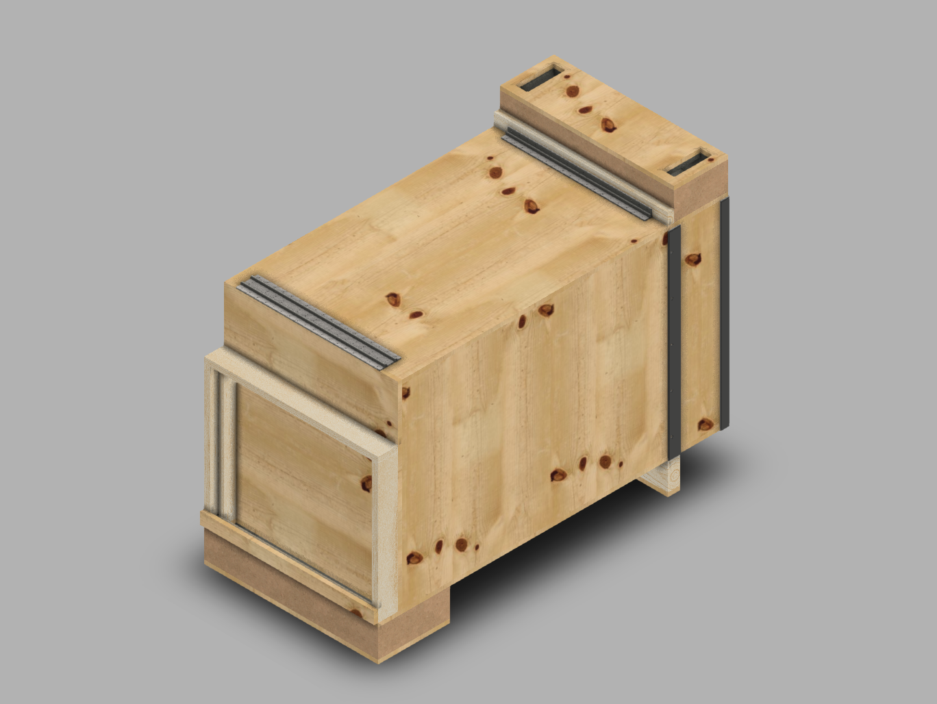
The main body of the rack is 21.875" wide, 25.375" tall, and 41.25" deep. This provides 12U of 30" deep rack space. The bottom supports add 4" of height, and the rear exhaust baffle (on top) adds another 4".
Structure
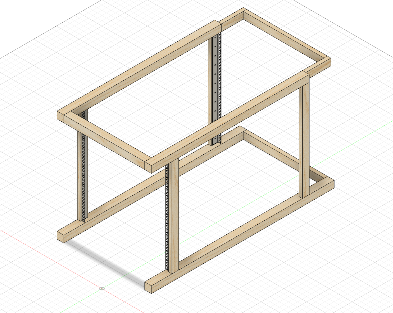
A box made entirely of plywood is a little tricky because screwing into the edge can cause it to split. So the rack is supported by a frame made of 2x2’s, and each plywood piece can be screwed through its face. I’ll probably also glue everything together for extra strength. The rack rails are screwed into 2x1’s, which are then attached vertically between top and bottom 2x2’s. The plywood on the side will also be screwed and glued to these. One subtlety to note is that the side pieces of plywood sit in between the top and bottom pieces so load is transfered through the sides from top to bottom. It probably doesn’t matter much since there’s not much weight on top, but might as well do it right. The other notable detail is the half-width section of the frame near the back. This is to allow space for the sound-proofing material on the side panels, which is described later.
Front Door
The front door uses a double piano hinge to allow it to rotate 270° and rest on top of the rack. Weather stripping and a couple latches (not pictured) will provide a tight seal between the door and the body. Putting hinges on the side for a “regular” door is also an option, and would probably be easier if you have the space.
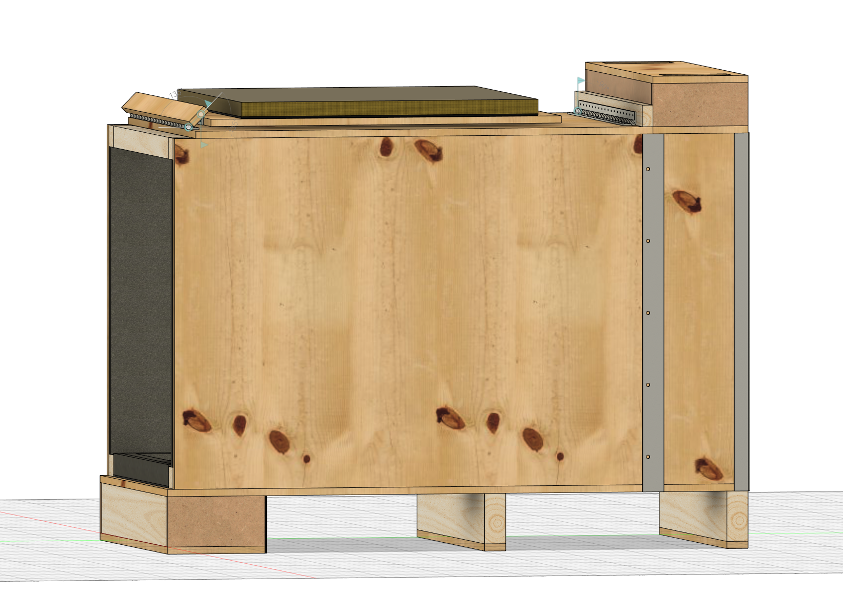
Rear Access
The rear side of the rack is accessed by rotating the exhaust baffle out of the way then removing some side panels. Note the additional 2x1 between the baffle and the hinge, which moves the axis of rotation further away so the baffle can move completely out of the way of the side panels. The side panels sit between some steel brackets and the interior frame to hold them in place when the rack is closed while still being easy to remove. The reason for doing this is to allow the rack to be placed in the corner of a room, for example. In my case, there are two 45° roof trusses on either side of the rack, and a wall behind it, so no kind of door would work.
Getting an airtight seal here is slightly less of a concern, since the outward airflow in the exhaust area will mostly prevent dust from entering. I plan on adding a little bit of weather stripping anyways, though, especially between the exhaust baffle and the side panels. I’ll use some latches here as well to hold the exhaust baffle and side panels down.
Sound Proofing
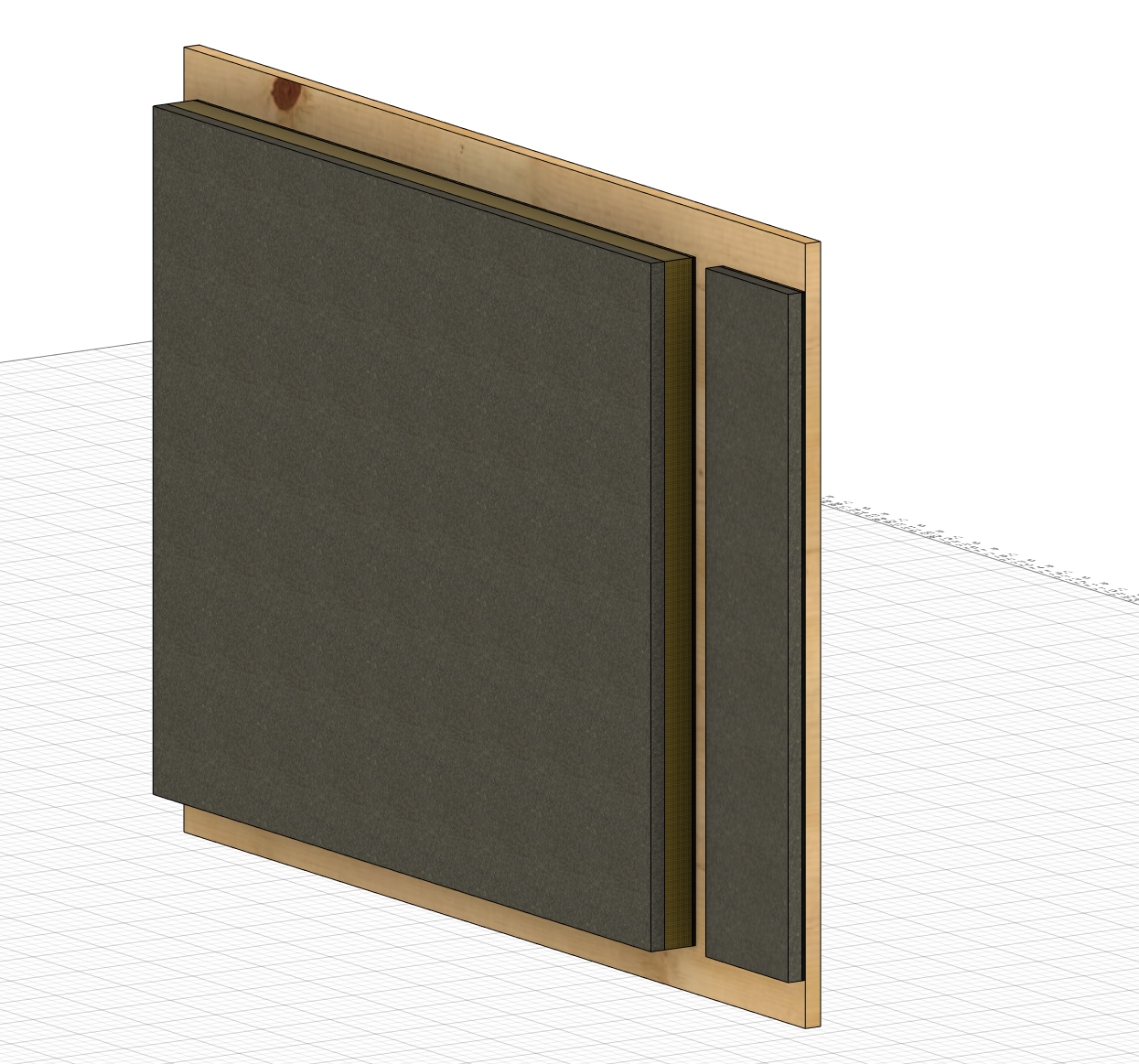
Sound proofing is achieved through three layers. The first is 1 lb MLV (Mass-Loaded Vinyl), which is 1/8" thick. This layer will be stapled to the plywood. It works by adding a lot of mass which absorbs the energy from the sound waves. The sound waves cause the MLV vibrate - separately from the plywood so it doesn’t transfer the sound - and somehow this reflects part of the sound waves back through the other layers for additional filtering.
The second layer is Owens Corning 703, which is a rigid fiberglass and resin board. This type of material is often used to soundproof recording studios, and generally serves as an insulator. I’m using 1" thick panels in this design. Rockwool is a similar alternative, depending on what’s available nearby.
The last layer is sound-proofing acoustic foam. This layer needed to be somewhat thin (0.5") to fit without making the rack larger, so the softer polyurethane foams, which are generally 1" at minimum, wouldn’t work. There are some thinner foams made of rubber, but they’re quite expensive.
Is this total overkill? Probably. It’s likely that just having it in a massive box will knock the sound levels down enough to make it inaudible, but its a homelab. It’s supposed to be overkill! I’m going to build the rack with the MLV first, install my equipment, and see how loud it is. If it still needs more, I’ll add the other layers one by one.
In some areas, there isn’t enough space for all three layers, so I’ll just use MLV and the foam.
Air Flow
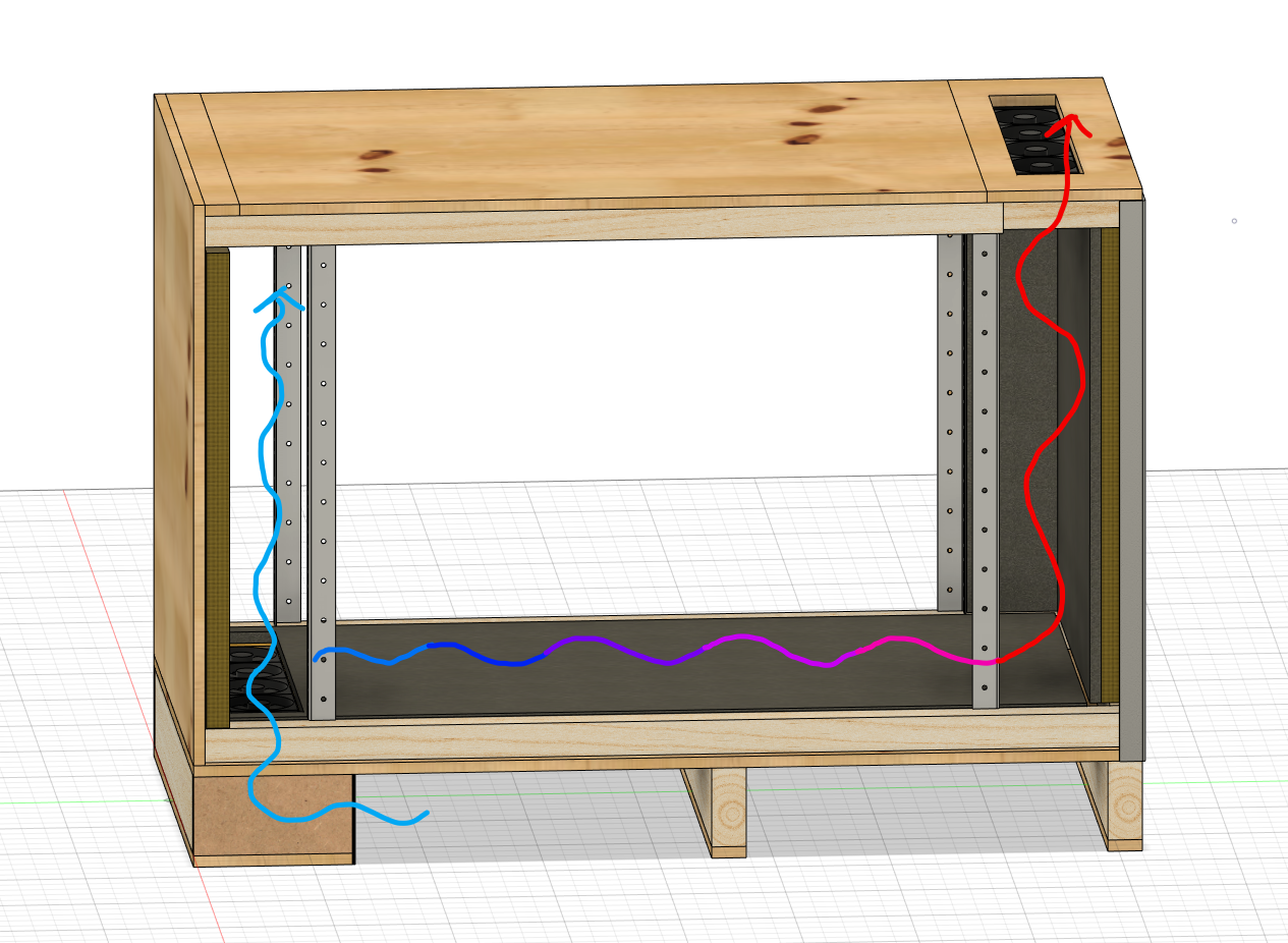
Since the box will be totally sealed off, air flow has to be carefully designed. Following some commercial soundproof rack designs, I put the five-fan intake in the front on the bottom to create a “wall” of cool air. This air is drawn through the rack equipment to the back, where another five fans blow the air out the top. For this scheme to work, it’s important that there aren’t any open spaces in the rack that would allow the intake and exhaust to mix, so I’ll have to cover up the few empty spots with blank plates.
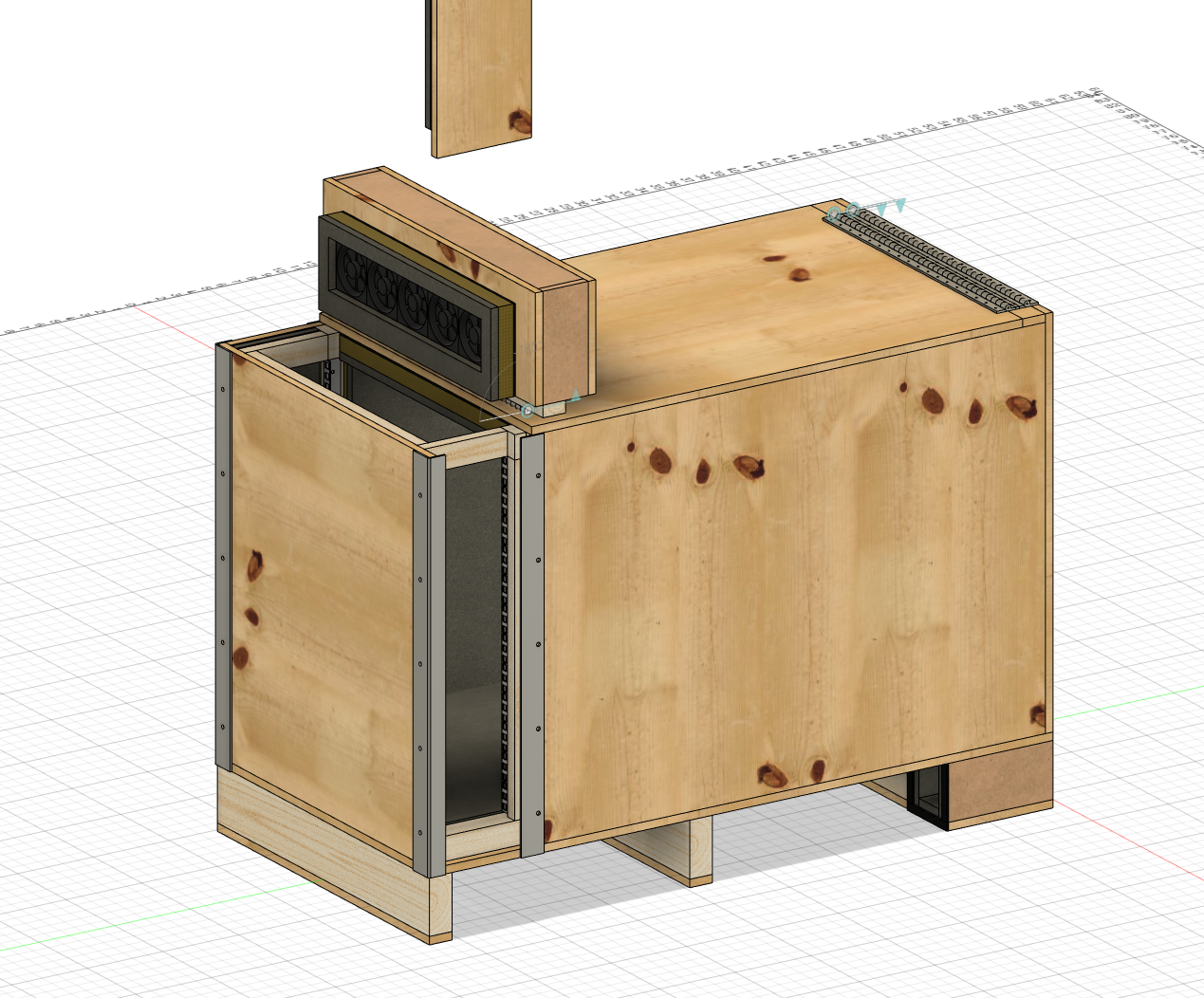
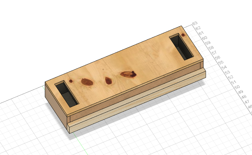
Intake Baffle
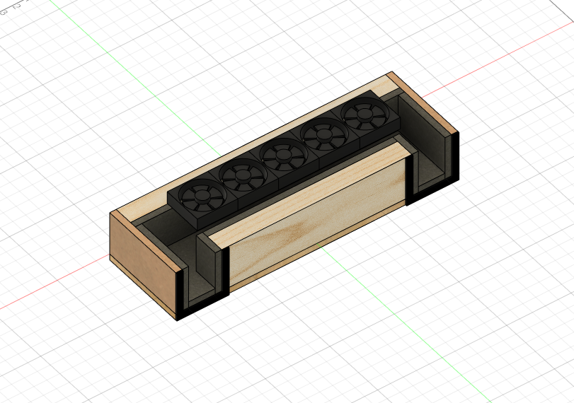
The Intake Baffle serves a few purposes. First, it helps with the soundproofing. Just having a large hole in the box would let some of the sound “leak” out, including the sound of the fans themselves. By adding several 90° turns lined with acoustic foam, the sound energy, especially at high frequencies, will get absorbed. It also directs the remaining sound towards the back of the rack, rather than the front. Similarly, it allows the intake air to be drawn from the bottom towards the middle of the box, away from potential obstructions or debris. Finally, some magnetic adhesive strips around the intake holes will be used to attached MERV-13 (or maybe -16) filter material to prevent dust from getting in.
Exhaust Baffle
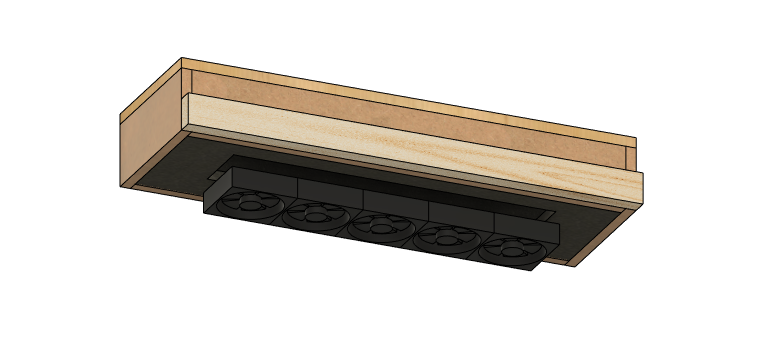
The Exhaust Baffle functions similarly to the Intake. It provides a quiet exhaust path for the hot air, and is placed on top to take advantage of convection. Since the rack will be placed against the wall, the exhaust holes are at the top rather than the back, but in applications where that’s not the case, this could be an exact copy of the Intake Baffle. Filtering isn’t necessary here since the pressure of the exhaust will keep dust out.
The exhaust baffle doesn’t hold any weight, so I’ve designed it with 1/2" MDF all around the sides. Because MDF is a fiber composite, it won’t split when you screw into the thin side. If you’re careful, you can go into the side of plywood, but since its 1/2" I just don’t want to worry about it.
Extras
There are a few critical things I didn’t add to the design, but I’ll mention them here for completeness. The first is a power source. You could pretty much add it anywhere convenient. My plan is to add an electrical box and outlet to the bottom of the rack near the back and wire it into an existing outlet in my attic with some romex. The other is connectivity. I need to bring in my coax cable for internet and provide a few jacks to connect the network to the rest of the house. I’m going to add a mud ring with a keystone jack wall plate on the bottom as well (I thought about putting it on the side, but then I’d have to disconnect everything every time I want to remove a side panel).
Cost
The materials needed are:
- 1/2" Plywood (4’x8’) - $60
- 1/2" MDF (1.5sqft needed) - $15
- 1x 8ft 2x4 - $8
- 2x 8ft 1x2 - $5
- 3x 8ft 2x2 - $15
- Piano Hinge - $20
- MLV (24sqft total) - $65
- Owens Corning 703 (24sqft total) - $20
- 8x Rubber Foam Acoustic Insulation 6"x6"x0.5" 16-pack (32sqft total) - $120
- 2x 3M VHB Heavy Duty Mounting Tape - $24
- 12V, 2A AC DC Power Supply - $8
- 2x 80mm Case Fan 5-pack - $30
- Flexible Magnetic Tape - $7
Summary
- Lumber: $103
- Sound-proofing: $229
- Fans: $38
- Misc: $27
Total: $397
Some notes: the design calls for just slightly over 32sqft of plywood, which is almost exactly one sheet. You always want extra because inevitably you’ll make a mistake somewhere along the line and need more material. Rather than buy an entire second sheet, you can either get a smaller “hobby” board, or use some scraps that you might already have on hand, which is what I’ll do. For the MDF, the design only needs 1.5sqft, but it might be hard to find a small piece. You could just use more plywood and be careful about splitting the edges (definitely pre-drill screw holes), or maybe use some other material. A baseboard or small piece of hardwood might be cheaper. Also, Owens Corning 703 comes in boxes of 12, but the design only needs 3 pieces, so I quoted 1/4 the price of a box. I haven’t actually found any online retailers that will sell by the piece, though.
Obviously I blew the cost target out of the water. I was expecting about $100 for lumber, $100 for sound-proofing, and $100 for everything else. Turns out sound-proofing material is expensive. The MLV could be replaced with butyl rubber sound deadening mats designed for cars. These can be cheaper than MLV because you can find smaller quantities, but they are less dense and only 80mil thick, meaning they aren’t as sound-proof. The rubber foam acoustic insulation is what really breaks the bank. I found two potential alternatives. First: 1/2", 2LB density polyethylene foam rolls, which would be about $60 total, but I expect its less dense than the rubber foam. The other is a 1/2" polyester felt fabric acoustic panel, which would be about $86 total. These claim a density of 230kg/m^3, which is actually 3x better than the acoustic foam which is about 71kg/m^3!
Next Steps
Now that the design is complete, I am going to do some airflow testing to make sure the fans I’ve purchsed can provide enough air to keep up with the fans in my R720XD. I checked the fan’s spec sheet, and while it does provide a PQ Curve, I have no way of measuring the pressure so I can’t tell what the expcted airflow is. They’re definitely very beefy fans, but they’re also heavily obstructed, so I don’t think the flow rate is much higher than what these 80mm fans can provide. However, there’s also the issue of the restriction caused by the intake baffle and filter material. Both baffles have the same cross-sectional area, so the mass of air being pulled into the rack should roughly be equal to the mass of air being exhausted, which will avoid any excessive pressure in the system.
I’m going to build a test version of the intake baffle by itself and attach the fans to it. I’ll generally just observe how much air is coming through the fans when it’s attached to the baffle versus when it’s in free air. I’m also going to hold it up to my R720XD intake. I figure if the baffle is spitting out more air than the R720XD can take in, it’ll blow out the sides. It might be a little bit janky, but better than nothing!